When a motor bearing fails, the motor heats up and lubrication begins to break down. The windings overheat and then the temperature sensor cuts out and stops the motor. Worst case, the shaft binds up, the rotor locks up and the motor fails completely.
Many predictive maintenance (PdM) programs use thermography to monitor the apparent temperatures of operational equipment, using the heat values to detect and avoid equipment loss. By using thermal imagers to capture two- dimensional infrared maps of bearing and housing temperatures, technicians can compare current operating temperatures to benchmarks and detect potential failures.
Fluke thermal imagers with IR-Fusion® technology fuses a visual, or visible light, image with an infrared image for better identification, analysis and image management. The dual images are accurately aligned heightening details, making it much easier to spot where further investigation is needed.
What to check?
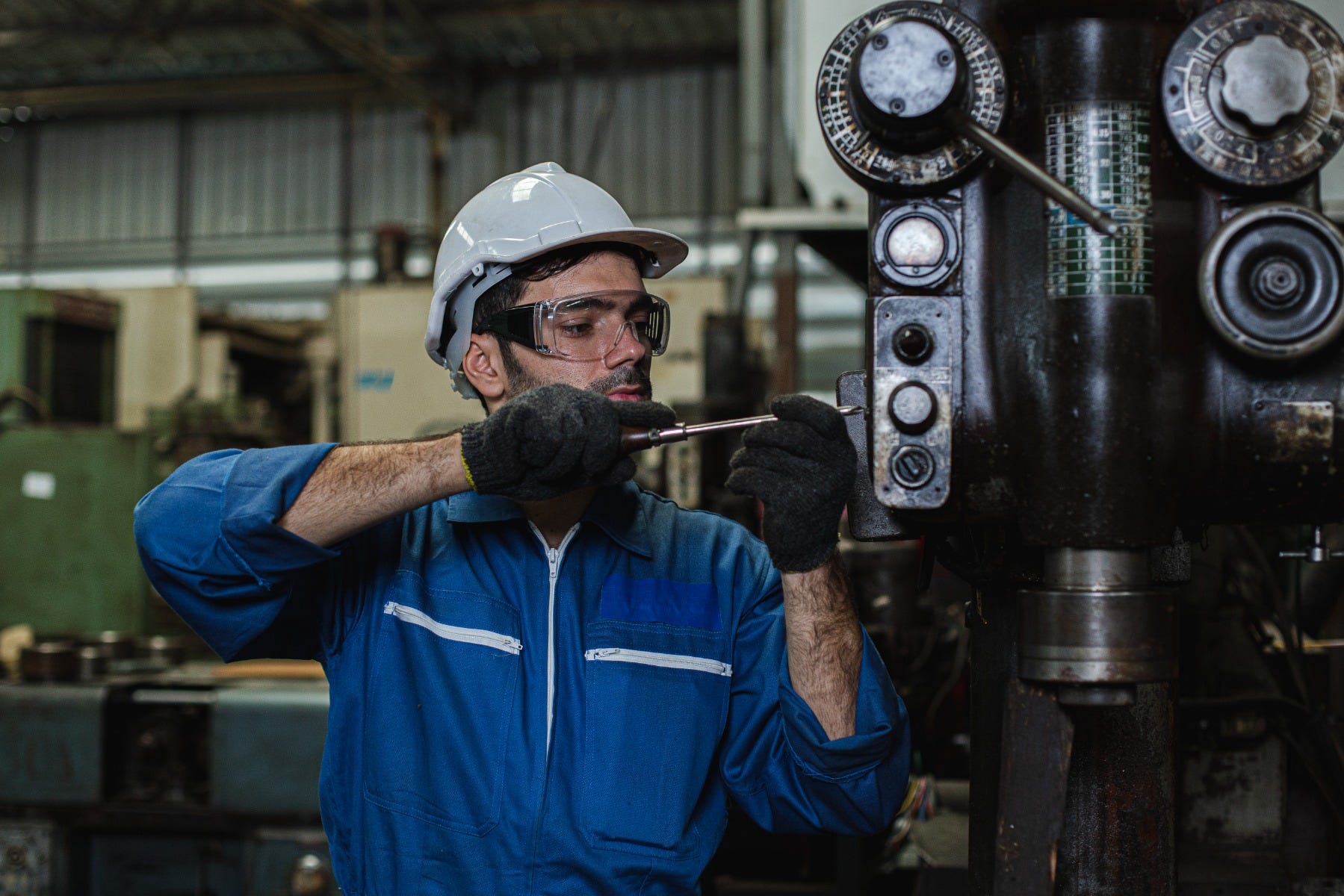
Generally speaking, vibration analysis is the PdM technology of choice for monitoring large, accessible, relatively high-speed bearings, but it can only be done safely when transducers can be placed on the bearings. For bearings that are relative small (e.g., in conveyor rollers), in low-speed operations, physically inaccessible or unsafe to get close to while the equipment is running, thermography is a good alternative to vibration analysis. In most cases, ther- mography can be performed at a safe distance while the equip- ment is operating. Capturing a thermal image with a handheld imager also takes less time than performing vibration analysis.
Mechanical equipment should be inspected when it has warmed up to steady state conditions and is running a normal load. That way, measurements can be interpreted at normal operating conditions. Capture a thermal image of the bearing to be checked, and if possible, capture images of bearings in the same area performing the same or a similar function, e.g., the bearing at the other end of a conveyor or paper machine roller or another pillow block on the same shaft.
What to look for?
Problems with bearings are usually found by comparing the surface temperatures of similar bearings working under similar conditions. Overheating conditions appear as “hot spots” within an infrared image and are usually found by comparing similar equipment. In checking motor bearings, this procedure entails comparing end bell to end bell (for motors and bearings of the same type) or stator to end bell temperatures.
In general, it is a good idea to create a regular inspection route that includes all critical rotating equipment. If a route for regular vibration analysis already exists, thermography can be added easily to these existing bearing-monitoring efforts. In any case, save a thermal image of each piece of key equipment on a computer and track your measurements over time, using the software that comes with the thermal imager. That way, you’ll have baseline images for comparison. They will help you determine whether a hotspot is unusual or not and help you verify when repairs are successful.
Imaging tip
Modify equipment guards and covers on conveyor systems and drive components so that bearings and couplings can be inspected using thermography. Consider installing a small, hinged door or using metal mesh instead of solid metal. In making any of these kinds of changes, be sure not to compromise personnel’s safety.
What represents a "red alert?"
Equipment conditions that pose a safety risk should take the highest repair priority. Beyond that, determining when action is required in your facility to keep a bearing from causing the loss of a crucial piece of equipment is an case-by-case undertaking that gets easier with experience. For example, on one difficult-to-monitor line, an auto manufacturer moved from vibration analysis to a combination of vibration and thermography to determine that normal operating temperatures for bearings on the line fell within a specific range. The company’s PdM personnel, well trained in thermography, now treat a bearing running above the upper limit of the normal operating range as an “alarm” situation.
When using thermography on bearings not normally monitored using vibration analysis or even when spot-checking bearings, try to follow the lead of the automotive company and estab- lish some “alarm” criteria, as you would for other condition-monitoring technologies. Some ther- mography experts, for example, have established rules-of-thumb for allowable temperature dif- ferentials ((Ts) for bearings on specific types of equipment using specific lubrication techniques (grease, oil bath, etc.).)
What's the potential cost of failure?
For a failed bearing in a specific motor, pump, drive or some other critical component, you can do analysis of the cost of the repair, lost pro- duction opportunity and lost labor costs. At one automotive facility, the estimated cost of the failure of a specific pump is more than $15,000 for repairs plus lost production of $30,000 per minute and labor costs of more than $600 per minute. Keeping that pump running is worth the effort.
Follow-up actions
All rotating equipment generates heat at the friction-bearing points in the system – the bearings. Lubrication reduces friction and thereby reduces and to varying degrees (depending upon the type of lubrication) dissipates the heat. Thermal imaging lets you literally “picture” this process while revealing the condition of bearings. When thermal images indicate an overheating bear- ing, you should generate a maintenance order to either replace the bearing or lubricate it. Vibration analysis or another PdM technology may help you determine the best course of action.
Whenever you discover a problem using a thermal imager, use the associated software to document your findings in a report, including a thermal image and a digital image of the equipment. That’s the best way to communicate problems you find and to suggest repairs.
Fluke. Keeping your world up and running.®
Fluke Corporation PO Box 9090, Everett, WA 98206 U.S.A. Fluke Europe B.V. PO Box 1186, 5602 BD Eindhoven, The Netherlands For more information call: In the U.S.A. (800) 443-5853 or Fax (425) 446-5116 In Europe/M-East/Africa +31 (0) 40 2675 200 or Fax +31 (0) 40 2675 222 In Canada (800)-36-FLUKE or Fax (905) 890-6866 From other countries +1 (425) 446-5500 or Fax +1 (425) 446-5116 Web access: http://www.fluke.com
©2005-2007, 2015 Fluke Corporation. Specifications subject to change without notice. Printed in U.S.A. 8/2015 2519603c-en
Modification of this document is not permitted without written permission from Fluke Corporation.